While the incoming power from your data center to an AWS Outposts rack is standard AC, within each rack, the servers are all supplied via a DC power bus. This differs from standard AC Power Distribution Units (PDUs) found inside the racks of most on-premises data centers.
In a standard AC PDU, AC power is converted into DC power using power supplies within the servers. With a DC power bus, this conversion is done centrally. Physical servers in an AWS Outposts rack do not need individual power supplies. This increases the efficiency of power utilization, thereby improving the cost-effectiveness and sustainability parameters of the physical footprint.
Don’t worry about the specifics; each rack in a deployment will arrive preconfigured appropriately. If you ever order additional servers to expand a rack, an AWS installer will handle this cabling and all of the calculations involved.
Outpost networking devices (ONDs) and customer networking devices (CNDs)
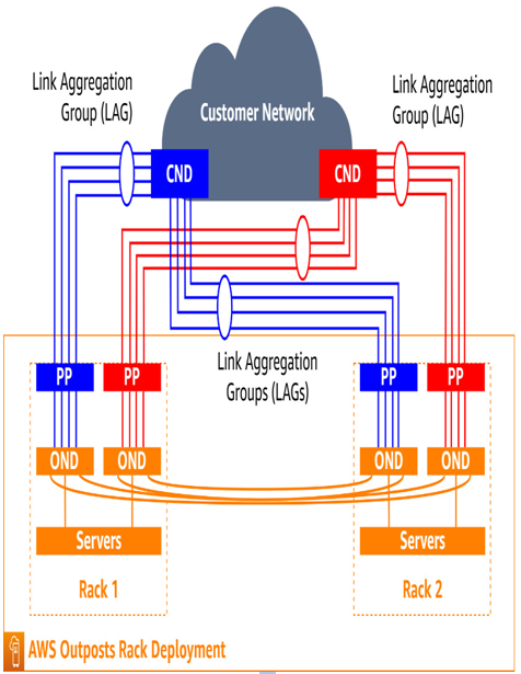
Each rack has two top-of-rack switches installed; these are referred to as ONDs. Two switches that meet the requirements outlined in the User Guide for racks are designated as CNDs.
At the physical network layer, a leaf/spine topology is used between all racks in a deployment. Each OND is interconnected to all others in a deployment to form the leaves. Further, each rack is connected to both CNDs, which act as the spine.
It is recommended that each OND within a given rack is connected to a separate CND via a top-of-rack Patch Panel (PP) to provide network diversity for both logical and physical connections:

Figure 5.2 – Leaf/spine topology between ONDs and CNDs
It is further recommended that each of these links be more than one physical cable configured in a Link Aggregation Group (LAG), also known as an IEEE 802.1q Ethernet trunk. Note that even if only one cable is used for a given link, a LAG for it is still provisioned to allow the customer to add additional links later more easily. The preceding figure illustrates this concept.
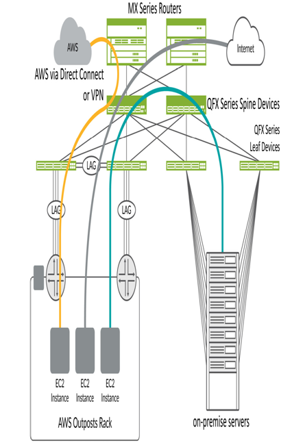
Customers can work with network hardware vendors that offer specific solutions for AWS Outposts Rack. This helps smooth the deployment with proven configurations. One example is Juniper Networks. Juniper provides documentation that walks customers through configuring their QFX Series devices to interoperate with AWS Outposts. Juniper suggests leveraging their QFX5000 Series in a top-of-rack position and either the QFX5000 or the QFX10000 Series in the spine role for use with AWS Outposts. Using this configuration will enable customers to deploy data center fabric capable of providing 400G connectivity while providing 100G connectivity to single Outposts racks. The following figure depicts the suggested integration of Juniper QFX Series devices and AWS Outposts racks:

Figure 5.3 – Juniper QFX Series devices and AWS Outposts racks 1
1 Image Credit Juniper Networks
The orange path in the preceding figure shows the path EC2 instances in an AWS Outposts rack take to natively access AWS resources. The gray path shows how EC2 instances can access the internet or enterprise WAN. Finally, the green path shows the way EC2 instances can reach on-premises resources locally.

